对 RIP 进行了全方位的原理讲解,但仅仅知道什么 RIP 是不够用的,现在来分享下 RIP 是怎么用的,即 RIP 网络实操,看看这些技术是怎么在网络设备上面实现的,如何用 RIP 解决实际的网络问题。
RIPv2 基础配置
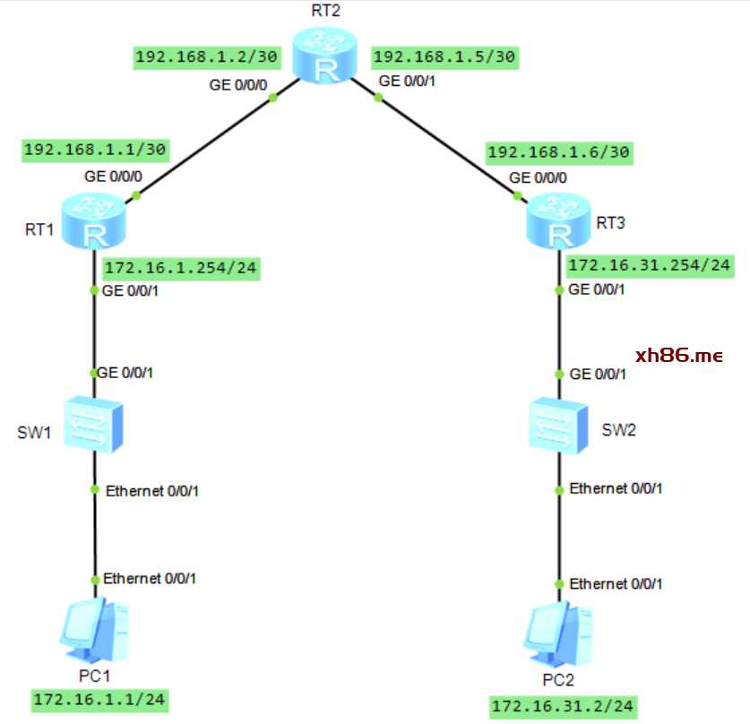
下面的拓扑图中有三台路由器,我们在路由器上部署 RIPv2 ,让网络中的各个网段能够实现互通。
RT1 配置:
<Huawei>system-view
[Huawei]sysname RT1
[RT1]interface GigabitEthernet 0/0/0
[RT1-GigabitEthernet0/0/0]ip address 192.168.1.1 30
[RT1-GigabitEthernet0/0/0]quit
[RT1]interface GigabitEthernet 0/0/1
[RT1-GigabitEthernet0/0/1]ip address 172.16.1.254 24
[RT1-GigabitEthernet0/0/1]quit
[RT1]
[RT1]rip 1
[RT1-rip-1]version 2
[RT1-rip-1]network 192.168.1.0
[RT1-rip-1]network 172.16.0.0
配置说明:
rip 1 :数字 1 表示 RIP 的进程 ID 。如果不配置,系统会自动生成一个。一个设备运行不同 RIP 进程,使用进程 ID 区分,且相互独立。
version 2 :配置 RIP 的版本,这里配置的是 RIPv2 。
network 192.168.1.0 :network 命令用于网段的激活。
network 172.16.0.0 :需要注意的是 network 命令指定的必须是主类网络地址,而不是子网地址。如果使用 network 172.16.1.0 命令,那么系统会报错,因为 172.16.1.0 是一个子网地址,而不是主类地址。
RT2 配置:
[RT2]rip 1
[RT2-rip-1]version 2
[RT2-rip-1]network 192.168.1.0
配置说明:
network 192.168.1.0 :同时激活了 192.168.1.0/30 和 192.168.1.4/30 这两个网段。
RT3 配置:
[RT3]rip 1
[RT3-rip-1]version 2
[RT3-rip-1]network 192.168.1.0
[RT3-rip-1]network 172.16.0.0
R1 、R2 和 R3 配置完成后,就会在相应接口发送 Request 和 Response 报文,并进行路由学习。
检查配置
配置完成后,其实并不知道配置是否有效,这时就需要使用检查命令,查看配置是否正确、功能是否生效。使用 display rip 1 interface 命令,查看设备哪些接口激活了 RIP 。
比如查看 RT1 :
<RT1>display rip 1 interface
————————————————————————–
Interface IP Address State Protocol MTU
————————————————————————–
GE0/0/1 172.16.1.254 UP RIPv2 Multicast 500
GE0/0/0 192.168.1.1 UP RIPv2 Multicast 500
<RT1>
上面可以看出,R1 的 GE0/0/0 和 G/0/01 接口都已激活。
还可以使用 display rip 1 database 命令查看 RIP 进程 1 的数据库。
比如查看 RT1 :
<RT1>display rip 1 database
—————————————————
Advertisement State : [A] – Advertised
[I] – Not Advertised/Withdraw
—————————————————
172.16.0.0/16, cost 0, ClassfulSumm
172.16.1.0/24, cost 0, [A], Rip-interface
172.16.31.0/24, cost 2, [A], nexthop 192.168.1.2
192.168.1.0/24, cost 0, ClassfulSumm
192.168.1.0/30, cost 0, [A], Rip-interface
192.168.1.4/30, cost 1, [A], nexthop 192.168.1.2
<RT1>
上面可以看出,R1 发现了直连网段 172.16.1.0/24 和 192.168.1.0/30 ,度量值为 0 。RT1 还通过 RIP 学习到 172.16.31.0/24 和 192.168.1.4/30 ,度量值分别为 2 跳和 1 跳。
最后使用 display ip routing-table protocol rip 命令,检查三个路由器学习到的 RIP 路由。
查看 RT1 的 RIP 路由:
<RT1>display ip routing-table protocol rip
Route Flags: R – relay, D – download to fib
——————————————————————————
Public routing table : RIP
Destinations : 2 Routes : 2
RIP routing table status : <Active>
Destinations : 2 Routes : 2
Destination/Mask Proto Pre Cost Flags NextHop Interface
172.16.31.0/24 RIP 100 2 D 192.168.1.2 GigabitEthernet0/0/0
192.168.1.4/30 RIP 100 1 D 192.168.1.2 GigabitEthernet0/0/0
RIP routing table status : <Inactive>
Destinations : 0 Routes : 0
<RT1>
查看 RT2 的 RIP 路由:
<RT2>display ip routing-table protocol rip
Route Flags: R – relay, D – download to fib
——————————————————————————
Public routing table : RIP
Destinations : 2 Routes : 2
RIP routing table status : <Active>
Destinations : 2 Routes : 2
Destination/Mask Proto Pre Cost Flags NextHop Interface
172.16.1.0/24 RIP 100 1 D 192.168.1.1 GigabitEthernet0/0/0
172.16.31.0/24 RIP 100 1 D 192.168.1.6 GigabitEthernet0/0/1
RIP routing table status : <Inactive>
Destinations : 0 Routes : 0
<RT2>
查看 RT3 的 RIP 路由:
<RT3>display ip routing-table protocol rip
Route Flags: R – relay, D – download to fib
——————————————————————————
Public routing table : RIP
Destinations : 2 Routes : 2
RIP routing table status : <Active>
Destinations : 2 Routes : 2
Destination/Mask Proto Pre Cost Flags NextHop Interface
172.16.1.0/24 RIP 100 2 D 192.168.1.5 GigabitEthernet0/0/0
192.168.1.0/30 RIP 100 1 D 192.168.1.5 GigabitEthernet0/0/0
RIP routing table status : <Inactive>
Destinations : 0 Routes : 0
<RT3>
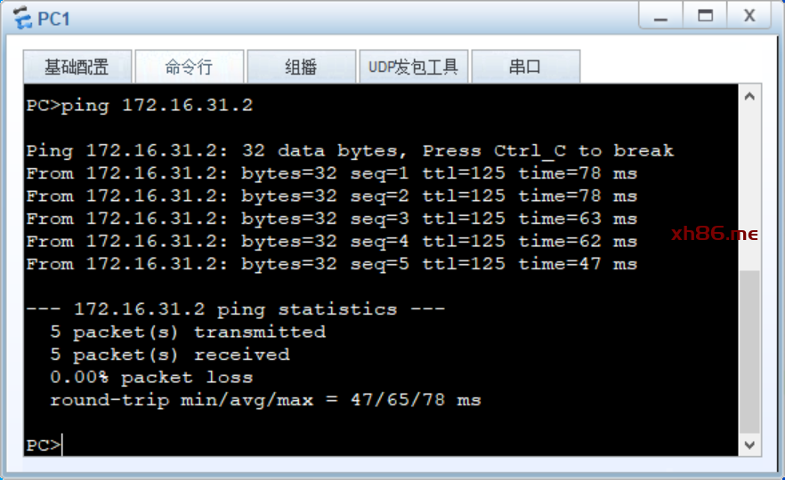
PC1 ping PC2 ,可以正常 ping 通,实验成功。
RIP 路由手动汇总
RIP 的路由自动汇总功能是把子网路由汇总成主类网络路由,存在路由汇总不准确的情况,导致报文不能正确转发到目的地,影响网络正常通信。这时,我们就可以使用路由手工汇总,准确的汇总路由,确保网络中的路由正常。
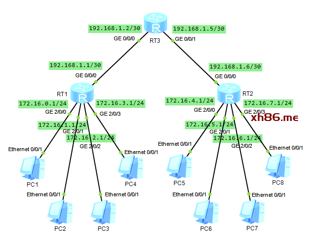
RT1 和 RT2 是两台汇聚层路由器,分别下联 4 个终端网段,上联核心路由器 RT3 。我们在三台路由器上部署 RIPv2 ,让路由器动态学习全网的路由。
RT1 配置
[RT1]rip 1
[RT1-rip-1]version 2
[RT1-rip-1]network 192.168.1.0
[RT1-rip-1]network 172.16.0.0
RT3 配置
[RT3]rip 1
[RT3-rip-1]version 2
[RT3-rip-1]network 192.168.1.0
RT2 配置
[RT2]rip 1
[RT2-rip-1]version 2
[RT2-rip-1]network 192.168.1.0
[RT2-rip-1]network 172.16.0.0
配置完成后,查看每一台路由器学习到的 RIP 路由。
查看 RT1 的 RIP 路由:
<RT1>display ip routing-table protocol rip
Route Flags: R – relay, D – download to fib
——————————————————————————
Public routing table : RIP
Destinations : 5 Routes : 5
RIP routing table status : <Active>
Destinations : 5 Routes : 5
Destination/Mask Proto Pre Cost Flags NextHop Interface
172.16.4.0/24 RIP 100 2 D 192.168.1.2 GigabitEthernet0/0/0
172.16.5.0/24 RIP 100 2 D 192.168.1.2 GigabitEthernet0/0/0
172.16.6.0/24 RIP 100 2 D 192.168.1.2 GigabitEthernet0/0/0
172.16.7.0/24 RIP 100 2 D 192.168.1.2 GigabitEthernet0/0/0
192.168.1.4/30 RIP 100 1 D 192.168.1.2 GigabitEthernet0/0/0
RIP routing table status : <Inactive>
Destinations : 0 Routes : 0
<RT1>
查看 RT2 的 RIP 路由:
<RT2>display ip routing-table protocol rip
Route Flags: R – relay, D – download to fib
——————————————————————————
Public routing table : RIP
Destinations : 5 Routes : 5
RIP routing table status : <Active>
Destinations : 5 Routes : 5
Destination/Mask Proto Pre Cost Flags NextHop Interface
172.16.0.0/24 RIP 100 2 D 192.168.1.5 GigabitEthernet0/0/0
172.16.1.0/24 RIP 100 2 D 192.168.1.5 GigabitEthernet0/0/0
172.16.2.0/24 RIP 100 2 D 192.168.1.5 GigabitEthernet0/0/0
172.16.3.0/24 RIP 100 2 D 192.168.1.5 GigabitEthernet0/0/0
192.168.1.0/30 RIP 100 1 D 192.168.1.5 GigabitEthernet0/0/0
RIP routing table status : <Inactive>
Destinations : 0 Routes : 0
<RT2>
查看 RT3 的 RIP 路由:
<RT3>display ip routing-table protocol rip
Route Flags: R – relay, D – download to fib
——————————————————————————
Public routing table : RIP
Destinations : 8 Routes : 8
RIP routing table status : <Active>
Destinations : 8 Routes : 8
Destination/Mask Proto Pre Cost Flags NextHop Interface
172.16.0.0/24 RIP 100 1 D 192.168.1.1 GigabitEthernet0/0/0
172.16.1.0/24 RIP 100 1 D 192.168.1.1 GigabitEthernet0/0/0
172.16.2.0/24 RIP 100 1 D 192.168.1.1 GigabitEthernet0/0/0
172.16.3.0/24 RIP 100 1 D 192.168.1.1 GigabitEthernet0/0/0
172.16.4.0/24 RIP 100 1 D 192.168.1.6 GigabitEthernet0/0/1
172.16.5.0/24 RIP 100 1 D 192.168.1.6 GigabitEthernet0/0/1
172.16.6.0/24 RIP 100 1 D 192.168.1.6 GigabitEthernet0/0/1
172.16.7.0/24 RIP 100 1 D 192.168.1.6 GigabitEthernet0/0/1
RIP routing table status : <Inactive>
Destinations : 0 Routes : 0
<RT3>
RIPv2 支持路由自动汇总,在 RIP 配置视图下,使用 summary 命令激活功能。默认状态是已经激活了。
我们查看下 RT1 的 RIP 协议信息。
<RT1>display rip
Public VPN-instance
RIP process : 1
RIP version : 2
Preference : 100
Checkzero : Enabled
Default-cost : 0
Summary : Enabled
Host-route : Enabled
Maximum number of balanced paths : 4
Update time : 30 sec Age time : 180 sec
Garbage-collect time : 120 sec
Graceful restart : Disabled
……
我们发现 RT1 的路由自动汇总功能已经激活,但是为什么路由条目依然是明细路由?这是因为在华为设备上,接口默认开启了 RIP 水平分割功能。为了防止环路和不连续子网问题的产生,在启动了水平分割或毒性逆转的接口上,RIPv2 的默认自动汇总功能会失效,所以路由器上看到的依然是明细路由条目。
查看 RT1 的 GE0/0/0 接口 RIP 信息:
<RT1>display rip 1 interface GigabitEthernet 0/0/0 verbose
GigabitEthernet0/0/0(192.168.1.1)
State : UP MTU : 500
Metricin : 0
Metricout : 1
Input : Enabled Output : Enabled
Protocol : RIPv2 Multicast
Send version : RIPv2 Multicast Packets
Receive version : RIPv2 Multicast and Broadcast Packets
Poison-reverse : Disabled
Split-Horizon : Enabled
Authentication type : None
Replay Protection : Disabled
<RT1>
为了让 RT1 的路由自动汇总生效,不通告明细路由,只通告汇总路由,可以关闭 GE0/0/0 接口的水平分割:
[RT1]interface GigabitEthernet 0/0/0[RT1-GigabitEthernet0/0/0]undo rip split-horizon
这样 RT1 通告 172.16.0.0/16 的子网路由时,不会通告明细路由,直接通告主类网络路由 172.16.0.0/16 ,这就是路由自动汇总的效果。
在 RT3 上查看 RIP 路由:
<RT3>display ip routing-table protocol rip
Route Flags: R – relay, D – download to fib
——————————————————————————
Public routing table : RIP
Destinations : 6 Routes : 6
RIP routing table status : <Active>
Destinations : 6 Routes : 6
Destination/Mask Proto Pre Cost Flags NextHop Interface
172.16.0.0/16 RIP 100 1 D 192.168.1.1 GigabitEthernet0/0/0
172.16.4.0/24 RIP 100 1 D 192.168.1.6 GigabitEthernet0/0/1
172.16.5.0/24 RIP 100 1 D 192.168.1.6 GigabitEthernet0/0/1
172.16.6.0/24 RIP 100 1 D 192.168.1.6 GigabitEthernet0/0/1
172.16.7.0/24 RIP 100 1 D 192.168.1.6 GigabitEthernet0/0/1
192.168.1.0/24 RIP 100 1 D 192.168.1.1 GigabitEthernet0/0/0
RIP routing table status : <Inactive>
Destinations : 0 Routes : 0
<RT3>
这时发现 RT3 上到达 RT1 直连的 4 个网段的明细路由没有了,替代的是汇总路由 172.16.0.0/16 ,看出来 RT1 的路由自动汇总功能生效了。
但是接口的水平分割关闭,是一个隐患,因为路由防环依赖水平分割。
其实,可以使用 summary always 命令,始终执行路由自动汇总,不管水平分割或毒性逆转是否激活。
调整 RT1 的配置:
[RT1]interface GigabitEthernet 0/0/0
[RT1-GigabitEthernet0/0/0]rip split-horizon
[RT1-GigabitEthernet0/0/0]quit
[RT1]rip 1
[RT1-rip-1]summary always
调整 RT2 的配置:
[RT2]rip 1[RT2-rip-1]summary always
这样,RT1 和 RT2 都可以路由自动汇总。但是路由自动汇总不准确,产生网络问题。
查看 RT3 的路由:
<RT3>display ip routing-table protocol rip
Route Flags: R – relay, D – download to fib
——————————————————————————
Public routing table : RIP
Destinations : 1 Routes : 2
RIP routing table status : <Active>
Destinations : 1 Routes : 2
Destination/Mask Proto Pre Cost Flags NextHop Interface
172.16.0.0/16 RIP 100 1 D 192.168.1.1 GigabitEthernet0/0/0
RIP 100 1 D 192.168.1.6 GigabitEthernet0/0/1
RIP routing table status : <Inactive>
Destinations : 0 Routes : 0
<RT3>
RT1 和 RT2 的汇总路由都是 172.16.0.0/16 ,而且两条路由的度量值相等,这两条路由都会添加到路由表中,并且进行等价负载分担。那么发往 172.16.1.0/24 的数据包,可能会发给 RT2 ,导致报文丢失。
问题根本原因是自动汇总产生的路由不精确,汇总路由的只能是主类网络路由。这时,可以使用手动路由汇总。RT1 的 4 个网段是 172.16.0.0/24 ~ 172.16.3.0/24 是连续的子网,可以使用 172.16.0.0/22 进行汇总。同理,RT2 的 4 个网段,可以使用 172.16.4.0/22 汇总。
RT1 手动路由汇总配置:
[RT1]interface GigabitEthernet 0/0/0[RT1-GigabitEthernet0/0/0]rip summary-address 172.16.0.0 255.255.252.0
RT2 手动路由汇总配置:
[RT2]interface GigabitEthernet 0/0/0[RT2-GigabitEthernet0/0/0]rip summary-address 172.16.4.0 255.255.252.0
配置完成后,查看 RT3 的 RIP 路由:
Route Flags: R – relay, D – download to fib
——————————————————————————
Public routing table : RIP
Destinations : 2 Routes : 2
RIP routing table status : <Active>
Destinations : 2 Routes : 2
Destination/Mask Proto Pre Cost Flags NextHop Interface
172.16.0.0/22 RIP 100 1 D 192.168.1.1 GigabitEthernet0/0/0
172.16.4.0/22 RIP 100 1 D 192.168.1.6 GigabitEthernet0/0/1
RIP routing table status : <Inactive>
Destinations : 0 Routes : 0
<RT3>
RIP 报文认证
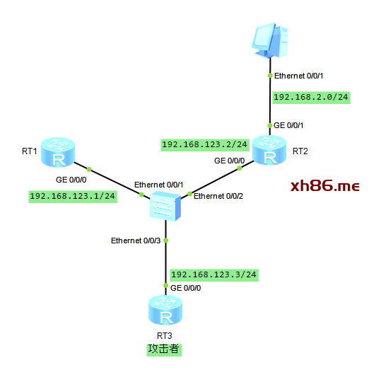
RT1 和 RT2 连接在一台交换机上,并开启 RIPv2 。正常情况下,RT1 能从 RT2 上获取 192.168.2.0/24 的路由。这时,出现了 RT3 这个攻击者,RT3 接入到交换机上,开启 RIPv2 ,并通告 192.168.2.0/24 的路由,那么 RT1 的路由表会受到影响。如果两条 192.168.2.0/24 路由的度量值相同,则会出现路由等价负责分担,发往这个网段的数据包可能会发送给 RT3 ,导致业务中断;如果 RT3 的跳数比 RT2 更新,就会刷新 RT1 的路由表,导致业务彻底中断。
这时就可以使用报文认证,RIPv2 支持报文认证,只要在 RT1 和 RT2 的接口上激活报文认证,就可以解决问题。
RT1 配置:
[RT1]rip 1
[RT1-rip-1]version 2
[RT1-rip-1]network 192.168.123.0
[RT1-rip-1]quit
[RT1]interface GigabitEthernet 0/0/0
[RT1-GigabitEthernet0/0/0]rip authentication-mode simple plain fox123
RT2 配置:
[RT2]rip 1
[RT2-rip-1]version 2
[RT2-rip-1]network 192.168.123.0
[RT2-rip-1]network 192.168.2.0
[RT2-rip-1]quit
[RT2]interface GigabitEthernet 0/0/0
[RT2-GigabitEthernet0/0/0]rip authentication-mode simple plain fox123
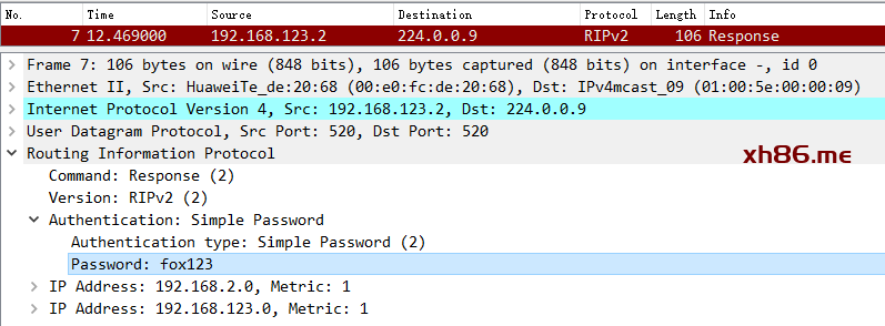
rip authentication-mode simple plain fox123 :这条命令用于激活 RIP 报文认证,simple 表示认证方式是简单认证,即明文认证,RIP 报文以明文的方式携带口令 fox123 。
plain 表示口令以明文方式存储在配置文件中,使用 display 命令查看配置文件时,可以直接看到配置的口令。
<RT1>display current-configuration interface
GigabitEthernet0/0/0
[V200R003C00]
#
interface GigabitEthernet0/0/0
ip address 192.168.123.1 255.255.255.0
rip authentication-mode simple plain fox123
#
return
<RT1>
传输和保存口令,都是明文方式,显然不安全。可以使用 cipher 替换 plain ,口令是以密文形式存储在配置文件中。
RT1 配置举例:
[RT1]interface GigabitEthernet 0/0/0
[RT1-GigabitEthernet0/0/0]rip authentication-mode simple cipher fox123
[RT1-GigabitEthernet0/0/0]display this
[V200R003C00]
#
interface GigabitEthernet0/0/0
ip address 192.168.123.1 255.255.255.0
rip authentication-mode simple cipher %$%$pSsy’6OeQ&-xUUMgo]/1sG<e%$%$
#
return
[RT1-GigabitEthernet0/0/0]
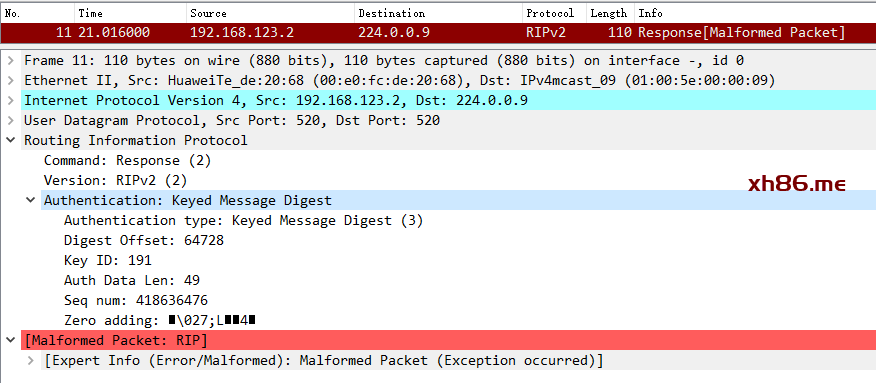
可以使用 md5 替换 simple,md5 有两个参数:usual 和 nonstandard ,usual 表示使用通用报文格式(私有协议),nonstandard 表示使用非标准报文格式( IETF 标准)。双方交互的 Response 报文不再以明文的方式携带,安全性得到提升。
RT1 配置:
[RT1]interface GigabitEthernet 0/0/0
[RT1-GigabitEthernet0/0/0]rip authentication-mode md5 usual cipher fox123
RT2 配置:
[RT2]interface GigabitEthernet 0/0/0
[RT2-GigabitEthernet0/0/0]rip authentication-mode md5 usual cipher fox123
查看 Response 报文:
附加度量值
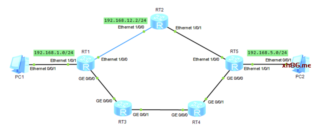
RT1 、RT2 、RT3 、RT4 和 RT5 都运行 RIP 协议,RT5 发布 192.168.5.0/24 路由。RT1 分别从 RT2 和 RT3 获取到这条路由,从 RT2 学到的路由度量值是 2 跳,从 RT3 学到的路由度量值是 3 跳,RT1 选择从 RT2 学到的 192.168.5.0/24 路由,因为路由的度量值更小。同理,RT5 优选 RT2 通告的 192.168.1.0/24 路由。
查看 RT1 的 RIP路由:
<RT1>display ip routing-table protocol rip
Route Flags: R – relay, D – download to fib
——————————————————————————
Public routing table : RIP
Destinations : 4 Routes : 5
RIP routing table status : <Active>
Destinations : 4 Routes : 5
Destination/Mask Proto Pre Cost Flags NextHop Interface
192.168.5.0/24 RIP 100 2 D 192.168.12.2 Ethernet1/0/0
192.168.25.0/24 RIP 100 1 D 192.168.12.2 Ethernet1/0/0
192.168.34.0/24 RIP 100 1 D 192.168.13.3 GigabitEthernet0/0/0
192.168.45.0/24 RIP 100 2 D 192.168.13.3 GigabitEthernet0/0/0
RIP 100 2 D 192.168.12.2 Ethernet1/0/0
RIP routing table status : <Inactive>
Destinations : 0 Routes : 0
<RT1>
这样的话,192.168.1.0/24 和 192.168.5.0/24 网段的流量是走在 RT1-RT2-RT5 这条百兆链路上,而 RT1-RT3-RT4-RT5 这条千兆链路上没有任何流量,实在不合理。更好的方法是将流量切换到千兆链路上,而百兆链路作为备份路径。
RIP 支持在接口上增加指定路由的度量值,影响 RIP 路由的选择。
RT1 的配置:
[RT1]acl 2000
[RT1-acl-basic-2000]rule permit source 192.168.5.0 0.0.0.0
[RT1-acl-basic-2000]quit
[RT1]interface Ethernet 1/0/0
[RT1-Ethernet1/0/0]rip metricin 2000 2
rip metricin 2000 2 :用于调整接口的附加度量值,当收到 ACL 匹配的路由更新时,度量值会在原来的基础上增加 2 跳。
这时,RT1 从 Ethernet1/0/0 接口收到的 192.168.5.0/24 路由时,度量值变为 4 ,于是 RT1 选择从 RT3 通告的 192.168.5.0/24 路由,因为路由度量值为 3 。
但是现在只完成了一半,从 192.168.1.0/24 到 192.168.5.0/24 的数据包走 RT1-RT3-RT4-RT5 这条路径,但是从 192.168.5.0/24 到 192.168.1.0/24 的数据包走 R5-R2-R1 这条百兆带宽路径,也就是数据的往返路径不一致。为了实现数据往返使用相同路径,我们需要进行相应调整,让 RT5 选择 RT4 通告的 192.168.1.0/24 路由。方法有两种:一种是在 RT5 的 Ethernet1/0/0 接口做配置,增加这条路由的度量值;另一种就是在 RT2 的 Ethernet1/0/1 接口做配置,增加这条路由的度量值。我们看下后面一种方法的配置:
[RT2]acl 2000
[RT2-acl-basic-2000]rule permit source 192.168.1.0 0.0.0.0
[RT2-acl-basic-2000]quit
[RT2]interface Ethernet 1/0/1
[RT2-Ethernet1/0/1]rip metricout 2000 3
rip metricout 2000 3 :用于调整接口的附加度量值,当发送 ACL 匹配的路由更新时,度量值会在原来的基础上增加 3 跳。
这时,RT2 通告给 RT5 的 192.168.1.0/24 路由的度量值从 2 跳变成 4 跳,RT5 选择 RT4 通告的路由(跳数为 3 )。这样就把流量引导到千兆带宽的路径上。
RIP 发布默认路由
通常连接 Internet 出口线路的路由器,会配置一条静态默认路由实现网络互联。
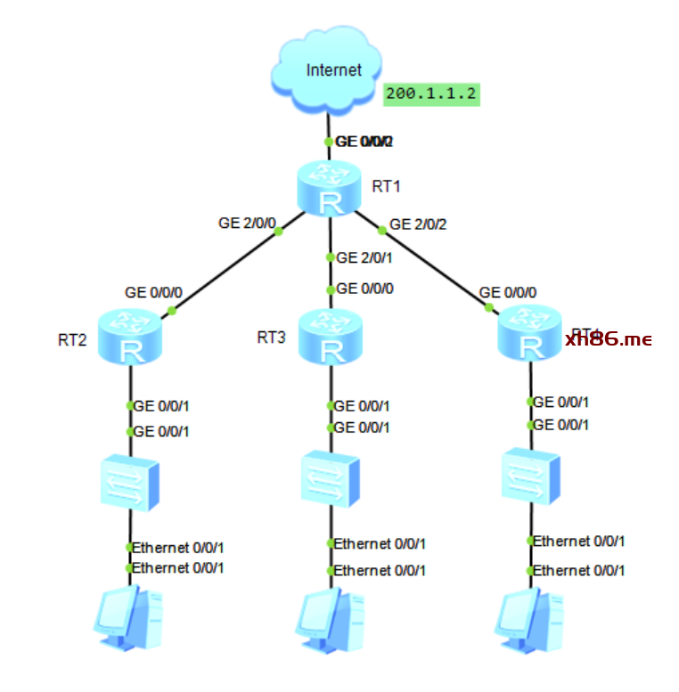
RT2 、RT3 和 RT4 下连终端设备,上连出口路由器 RT1 。在 4 台路由器上部署 RIPv2 ,实现各个网段互通。RT1 上配置一条指向 Internet 的静态默认路由,来访问 Internet 。那么 RT2 、RT3 和 RT4 下连终端设备访问 Internet 的流量,如何转发到 RT1 呢?一种方法是在 RT2 、RT3 和 RT4 配置下一跳是 RT1 的静态默认路由,但是这个方法不灵活,需要额外手动配置,而且静态默认路由无法感知网络拓扑的变化。还有一个更合适的方法:通过 RIP 传递默认路由,在 RT1 上通过 RIP 下发默认路由,从而让网络中的 RIP 路由器能够动态学习到这条默认路由。
RT1 关键配置:
[RT1]ip route-static 0.0.0.0 0.0.0.0 200.1.1.2
[RT1]rip
[RT1-rip-1]version 2
[RT1-rip-1]default-route originate cost 1
default-route originate cost 1 :在 RIP 发布一条默认路由,cost 表示默认路由的度量值,默认值为 0 。
完成配置后,在下连路由器上查看学习到的默认路由。RT2 的 RIP 路由如下:
<RT2>display ip routing-table protocol rip
Route Flags: R – relay, D – download to fib
——————————————————————————
Public routing table : RIP
Destinations : 5 Routes : 5
RIP routing table status : <Active>
Destinations : 5 Routes : 5
Destination/Mask Proto Pre Cost Flags NextHop Interface
0.0.0.0/0 RIP 100 2 D 192.168.12.1 GigabitEthernet0/0/0
……
这样,RT2 下连终端访问 Internet 时,流量会转发到 RT2 ,RT2 根据这条默认路由,转发给 RT1 ,RT1 根据静态默认路由将流量转发到 Internet 。
但是有个小问题,RT1 连接 Internet 的接口发生故障时,指向 Internet 的静态默认路由会失效,但 RT1 还会向 RIP 通告默认路由,导致下连的 Internet 流量会向上转发,最终在 RT1 处被丢弃。
这个问题可以通过 RT1 的配置解决,在 default-route originate 命令中增加 match default 。只有当 RT1 的路由表中有默认路由时,RT1 才会向 RIP 通告默认路由。这时,当 RT1 连接 Internet 的接口发生故障时,路由表的静态默认路由消失,RT1 会发布一条毒性路由来撤销之前发布的默认路由,这样下连的三台路由器就会把 RIP 默认路由删除。
RIP 路由标记
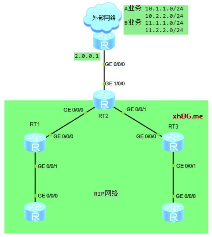
RT2 处于 RIP 域的边界,连接着一个外部网络,外部网络中有 A 、B 两个业务,分别使用不同的网段。RT2 通过静态路由到达两个业务网段,为了让整个 RIP 域动态学习到这些路由,RT2 需要将静态路由重分发到 RIP 。为了区分达到 A 、B 业务的路由,为它们设置不同的路由标记。
RT2 关键配置:
[RT2]ip route-static 10.1.1.0 24 2.0.0.1 tag 10
[RT2]ip route-static 10.2.2.0 24 2.0.0.1 tag 10
[RT2]ip route-static 11.1.1.0 24 2.0.0.1 tag 20
[RT2]ip route-static 11.2.2.0 24 2.0.0.1 tag 20
[RT2]rip
[RT2-rip-1]import-route static
ip route-static 10.1.1.0 24 2.0.0.1 tag 10 :设置 10.1.1.0 静态路由的标记值为 10 。
import-route static :将静态路由重分发到 RIP 中。静态路由的标记值会一并携带,并填充到 Response 报文的路由标记字段中。
查看 RT1 的路由表:
<RT1>display ip routing-table protocol rip
Route Flags: R – relay, D – download to fib
——————————————————————————
Public routing table : RIP
Destinations : 4 Routes : 4
RIP routing table status : <Active>
Destinations : 4 Routes : 4
Destination/Mask Proto Pre Cost Flags NextHop Interface
10.1.1.0/24 RIP 100 1 D 12.0.0.2 GigabitEthernet0/0/0
10.2.2.0/24 RIP 100 1 D 12.0.0.2 GigabitEthernet0/0/0
11.1.1.0/24 RIP 100 1 D 12.0.0.2 GigabitEthernet0/0/0
11.2.2.0/24 RIP 100 1 D 12.0.0.2 GigabitEthernet0/0/0
RIP routing table status : <Inactive>
Destinations : 0 Routes : 0
<RT1>
查看 10.1.1.0/24 路由的详细信息:
<RT1>display ip routing-table 10.1.1.0 verbose
Route Flags: R – relay, D – download to fib
——————————————————————————
Routing Table : Public
Summary Count : 1
Destination: 10.1.1.0/24
Protocol: RIP Process ID: 1
Preference: 100 Cost: 1
NextHop: 12.0.0.2 Neighbour: 12.0.0.2
State: Active Adv Age: 00h14m11s
Tag: 10 Priority: low
Label: NULL QoSInfo: 0x0
IndirectID: 0x0
RelayNextHop: 0.0.0.0 Interface: GigabitEthernet0/0/0
TunnelID: 0x0 Flags: D
<RT1>
上面可以看到路由携带的标记。
查看 RT1 的 RIP 数据库,查看外部路由及标记:
<RT1>display rip 1 database verbose
—————————————————
Advertisement State : [A] – Advertised
[I] – Not Advertised/Withdraw
—————————————————
10.0.0.0/8, cost 1, ClassfulSumm
10.1.1.0/24, cost 1, [A]
NextHop : 12.0.0.2 Intf : GigabitEthernet0/0/0
EntryID : 0xb4b3aeac Tag : 10
State : RM Active
10.2.2.0/24, cost 1, [A]
NextHop : 12.0.0.2 Intf : GigabitEthernet0/0/0
EntryID : 0xb4b3ae24 Tag : 10
State : RM Active
11.0.0.0/8, cost 1, ClassfulSumm
11.1.1.0/24, cost 1, [A]
NextHop : 12.0.0.2 Intf : GigabitEthernet0/0/0
EntryID : 0xb4b3ad9c Tag : 20
State : RM Active
11.2.2.0/24, cost 1, [A]
NextHop : 12.0.0.2 Intf : GigabitEthernet0/0/0
EntryID : 0xb4b3ad14 Tag : 20
State : RM Active
……
